
MOTION CONTROL SYSTEMS

Closing the Loop: A Practical Guide to the Actuonix LAC Board with P-Series Linear Actuators
Position-controlling a linear actuator sounds simple until you reach for the soldering
iron. A P-series Actuonix unit already knows where it is; the trouble is acting on that
knowledge. This is the board that does it for you, and this is how it wires up on the
bench.
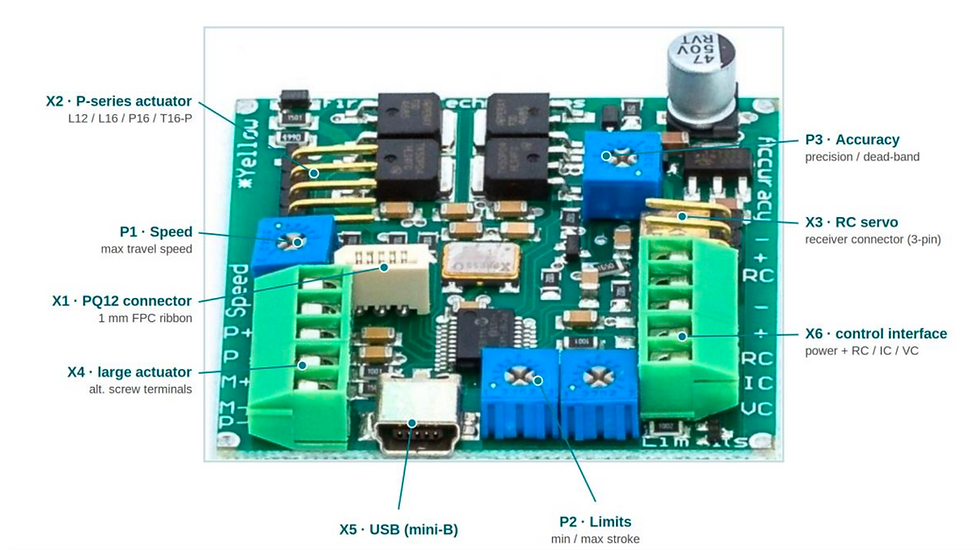
Figure 1 — The Actuonix LAC board, labelled per the datasheet: the X1–X6 connectors and the P1–P3 trim pots (Speed, Limits, Accuracy)
Why this little board earns its place
Linear actuators show up everywhere in motion design, camera rigs, valve and damper control, agricultural automation, robotic grippers, and test fixtures. The hard part is rarely the mechanics. It is the control: getting the rod to travel to a precise position and hold it there against load, without overshoot, chatter, or a stalled motor cooking itself.
You can solve that yourself. It means an H-bridge, a PWM scheme, an ADC reading the feedback element, a control loop you tune by hand, and current limiting so a jam does not destroy the gearbox. That is a respectable chunk of firmware and board space before your actual application gets a single line of code. The Actuonix Linear Actuator Control board, the LAC, collapses all of that into a 50 mm square that you talk to with a single command.
First, what makes an actuator “P-series”
The “P” in part numbers such as L12-P, PQ12-P, L16-P and P16-P stands for position feedback. Inside the actuator is a potentiometer mechanically tied to the rod, so the wiper voltage reports exactly how far the unit has extended. What a P-series actuator does not include is any electronics to read that feedback and drive the motor accordingly. It is, deliberately, a clean five-wire device: two motor leads and three potentiometer leads (a reference pair plus the wiper).
That split is the whole point. The actuator stays simple and rugged; the intelligence lives on whatever you pair it with. The LAC is purpose-built to be that partner, which is why the two are almost always specified together.
What the LAC actually does
The LAC is a self-contained, closed-loop position controller. You give it a target position; it reads the actuator’s built-in feedback, drives the motor to that target, and holds it. Internally, it runs a 10-bit dual-sample-rate quasi-PD algorithm in plain terms, a proportional-derivative style loop tuned for this family of actuators, so it behaves sensibly on the default settings without you touching a thing.
Two features matter more than the datasheet headline suggests. First, it self-detects its command interface on power-up, so the same board adapts to a hobby receiver, a PLC, or a laptop without rewiring jumpers. Second, it has stall detection: when an application briefly exceeds the actuator’s rated force, the board backs off rather than driving the motor into a wall, which directly extends actuator life on machines that occasionally hit a hard stop.
Specifications at a glance
Parameter | Value |
Control inputs | USB, RC servo, 1 kHz PWM (digital); 0–3.3 V, 4–20 mA (analog) |
Controller | 10-bit dual-sample-rate quasi-PD |
Compatible actuators | PQ12-P, L12-P, L16-P, P16-P, T16-P with position feedback (6 or 12 V); larger actuators with feedback at 12 or 24 V |
Board size | 50 mm × 50 mm (excluding the battery holder) |
Power input | 6–24 VDC, up to 4 A peak at 10% duty supply voltage must match the actuator’s rating |
Operating range | −10 to +70 °C, 10–80% relative humidity |
Five ways to command a position
The LAC accepts five distinct interface modes. You do not configure which one is active; the board figures it out (more on that below). Picking the right one is mostly about what is already in your system:
0–3.3 V analog. The simplest path. A voltage between ground and 3.3 V sets the target, so an external potentiometer or a microcontroller DAC maps directly to rod position. Hold the voltage to hold the position. Ideal for prototypes and basic home-automation rigs.
4–20 mA current loop. The language of industrial control. If your plant runs on PLCs and current-loop signaling, the LAC drops straight in: 4 mA is fully retracted, 20 mA is fully extended.
1 kHz PWM. This mode allows control of the actuator using a single digital output pin from an external microcontroller. The desired actuator position is encoded as the duty cycle of a 3.3-volt, 1-kHz square wave on LAC connector X6 pin 5, where the percent duty cycle sets the actuator position to the same percent of full stroke extension. 100% duty cycle represents full extension, and 0% duty cycle represents full retraction.
RC servo. Standard hobby-servo pulses, the same ones a Futaba or Hi-Tec receiver puts out. A 1 MS pulse fully retracts; a 2 MS pulse fully extends. Wire it through the dedicated 3-pin header, and the actuator behaves like an oversized servo.
USB. Connect the board to a PC for the most control. Beyond the commanding position,
USB mode unlocks the Advanced Configuration tuning we cover later. Custom settings are written to the board and survive a power cycle, so the actuator keeps your tuning even when the PC is gone.
In USB and digital modes, position is expressed on a 10-bit scale; 0 is fully retracted, and 1023 is fully extended. A value of 512 parks the rod at the halfway point, so on a 50 mm actuator that is roughly the 25 mm mark.
Wiring a P-series actuator to the board
A P-series actuator plugs into the X2 header, the gold pin header beside the yellow mark on the board. Its five conductors carry a fixed colour code:
Pin | Function | Wire Color |
1 | Potentiometer reference (negative) | Yellow |
2 | Motor terminal | Black |
3 | Motor terminal | Red |
4 | Potentiometer feedback (wiper) | Purple |
5 | Potentiometer reference (positive) | Orange |
Prefer the screw terminals? The X4 block silkscreened P+ / P / M+ / M− / P− takes the same actuator. Match each P-series wire to its function (the colour code on X4 differs, so wire by function, not colour):
X4 terminal | Function | P-series wire |
P+ | Potentiometer reference (positive) | Orange |
P | Potentiometer feedback (wiper) | Purple |
M+ | Motor terminal | Red |
M- | Motor terminal | Black |
P- | Potentiometer reference (negative) | Yellow |

Figure 2 — P-series actuator wiring at the X2 connector (per the Actuonix LAC datasheet)
Power and the command signal share the X6 control block. Connect your supply across the + and − terminals, positive to +, ground to −. The command lands on one of three signal terminals depending on the mode: RC for the servo pulse, IC for the 4–20 mA current loop, and VC for the 0–3.3 V analog voltage or the 1 kHz PWM. A hobby receiver can instead plug into the dedicated 3-pin X3 header. If you are feeding a bare signal rather than a self-powered source, tie its ground to the board’s ground; a floating reference is the most common reason a clean-looking setup simply will not move.
Direction tip: if the rod drives to one end and stops dead instead of seeking position, the motorleads are reversed relative to the feedback sense. Swap the two motor terminals, and it will behave. |
First power-up: the self-configuration trick
This is the behaviour that trips up most first-timers, so it is worth stating plainly. When the LAC powers on, it sweeps its inputs looking for a valid signal across all five interface modes. The first valid signal it finds wins; the board locks itself into that mode and disables every other input until the next power cycle.
The practical consequences:
Apply your command signal before or together with power, so the board latches onto the interface you actually intend to use.
If you change wiring, modes, or any of the on-board adjustments, cycle the power. Nothing takes effect until the board re-scans on the next boot.
A status light confirms the board has both power and a recognized command signal — if itstays dark, you are missing one of the two.
Recommended bring-up order: connect the actuator to X2 (or the X4 screw block), connect your command source, then apply power last. Confirm the light, command a mid-stroke position, and watch it seek.
Calibrating Performance with the On-Board Trim Pots
Four trim pots let you tune behaviour without a computer: speed, Accuracy, and a pair for the Limits. Each adjustment only registers after a power cycle, so set, re-power, observe, repeat.
Speed. Sets the maximum travel speed. Clockwise is faster; counter-clockwise is slower, useful for taking the aggression out of a light mechanism.
Limits (two pots). Software end-stops. One sets the minimum (retract) limit and the other the maximum (extend) limit; clockwise opens each toward full stroke. Any command that asks for more than these limits is clamped to them, which is a clean way to protect surrounding mechanics.
Accuracy. Sets the dead-band. Clockwise tightens it, so the actuator chases position in finer increments and settles more precisely. If the rod hunts or jitters around the target, the controller is being more precise than the actuator can resolve; ease the Accuracy back slightly, and it will settle. For finer control, move to USB tuning.
When you need more: USB advanced configuration
The trim pots are enough for most jobs, but the USB Advanced Configuration program is where you get surgical. Over USB, you can tune the controller’s response directly, including the proportional term that governs how aggressively the rod approaches its target. Raise it, and the actuator snaps to position faster; if it overshoots and oscillates before settling, ease it back down. There is a reset command to return to factory behaviour whenever a session goes sideways.
One important interaction: once custom USB settings are enabled, the on-board trim pots are ignored. The board honours your software configuration instead, and because those settings are stored on the board, they persist across power cycles and apply even when no PC is attached. That makes USB tuning a one-time setup step, not a permanent tether. Actuonix also publishes a DLL and an example LabVIEW project, so the same control can be folded into custom Windows software.
Critical Bench Warnings
Match the supply to the actuator. A 6 V actuator wants a 6 V supply; a 12 V actuator wants 12 V. The board’s 6–24 V range is the envelope, not a licence to overdrive a low voltage unit.
USB cannot power the motor. USB is fine for commanding and configuring, but it cannot source the actuator’s drive current. You still need a proper DC supply or battery on the power terminals.
Never power the RC header and the main input at once. If you drive the actuator from an RC receiver, do not also connect a separate supply to the control header. Two supplies with even slightly different voltages will push large currents between them. If you must run a separate supply, disconnect the receiver’s red power lead first.
Treat the board as ESD-sensitive. Work on a static-safe surface and handle it by the edges. It is a bare controller, not a consumer gadget.
Power-cycle after every change. Trim-pot tweaks, mode changes, rewiring, none of it applies until the board re-scans on the next boot. Saves a surprising amount of head scratching.
Where the LAC fits in a build
If your design only needs an actuator to reach a position and hold it, the LAC is the fastest route from a bare part to working motion.
No Firmware Burden: It removes the motor-control coding requirements entirely.
Universal Input: It adapts directly to whatever signaling your system already uses.
Hardware Protection: It protects your physical actuator using built-in stall detection.
For complex designs requiring coordinated multi-axis motion or tightly synchronized movement profiles, you may still need a dedicated master motion controller. However, for simple single-axis position control, this board is hard to beat on total cost and rapid development time.

Comments