
How Linear Actuators Work?


“How does an actuator work?” is one of the most common questions in motion design — and a fair one. Linear motion hides a surprising amount of mechanical nuance behind a simple-looking part. This guide breaks down the definition, internal components, and operating principles of an electric linear actuator so you know exactly what is happening inside the housing when one extends and retracts.
KEY TAKEAWAYS
|
What Is an Actuator?
Put simply, an actuator is a device that converts energy into motion. For an electric linear actuator, that means converting the rotary motion of an electric motor into linear motion — pushing or pulling along a straight line.

Figure 1 — Different types of Actuators
Electric motors are not new — they have been around for nearly 200 years. For most of that history, turning a motor's spin into straight-line movement meant building complex assemblies of gears, belts, pulleys, and rods. It was bulky, expensive, and fiddly to engineer.
The linear actuator changed that. It packages the whole rotary-to-linear conversion into a single, self-contained unit, sparing engineers and product designers the hassle of building a linear stage from oversized motors, servos, gears, and shafts.
The Core Principle: From Spin to Slide
An electric linear actuator is a mechanical device that converts an input signal into physical motion or force. It does this with a chain of mechanisms — motor, gears, screw, and nut — that step electrical energy down into smooth, controllable linear travel.

Figure 2 — Energy flow inside a linear actuator, from electrical input to useful work.
Inside a Linear Actuator: The Components
Most electric linear actuators operate in roughly the same way. Several key parts work together to turn rotation into linear motion. Here is what you will find inside a typical unit.

Figure 3 — Cutaway of a rod-style linear actuator with its six core components labeled.
How the parts work together
The motor generates rotational force, usually through a gearbox that sits between the motor and the lead screw. That gearbox is what determines the actuator's speed and force — different gearing produces different force/speed combinations.
The lead screw is where rotation becomes linear motion. It spins with the gearbox output shaft, and a captive block or nut mounted on it travels along the screw's length as it turns. On rod-style actuators, a rod assembly is fixed to that nut and rides up and down the screw with it.
Finally, an external housing encases everything — keeping the components aligned and protecting them from the elements. You will also often find extra electronics inside: end-limit switches, potentiometers, and supporting circuitry that vary from model to model.
Component reference
Component | What it does |
Electric motor | Generates the rotational force that drives everything downstream, usually a compact DC motor. |
Gearbox | Sits between the motor and the screw. The gear ratio sets the force-versus-speed balance of the actuator. |
Lead screw | The conversion stage: as it spins with the gearbox output shaft, its threads turn rotation into linear travel. |
Drive nut / captive block | Rides the lead screw and translates along it as the screw turns, carrying the load with it. |
Extending rod | Mounted to the nut on rod-style actuators; extends and retracts to deliver the stroke. |
External housing | Holds every part in alignment and shields the internals from dust, moisture, and impact. |
Feedback electronics | Optional limit switches, potentiometers, and control circuitry for positioning and end-of-travel sensing. |
ENGINEERING NOTE The lead screw is the heart of the device. Its pitch (travel per revolution) and thread type work together with the gearbox to define both how far the rod moves per motor turn and how much load it can hold — including whether the actuator is back-drivable under load. |
The Force vs. Speed Trade-off
When engineers talk about linear actuators, the conversation almost always lands on the trade-off between force and speed. Understanding what happens inside the actuator makes it clear why this trade-off exists — and why you rarely get both at once.
The gearbox is the lever. A high gear reduction multiplies torque into more pushing force but slows the output down. A low gear reduction gives faster travel but less available thrust. Same motor, different gearbox — very different actuator.

Figure 4 — Gear ratio determines where an actuator sits on the force-versus-speed scale.
Control and Feedback
Beyond the mechanical core, many actuators carry electronics that make them controllable and self-aware of their position. The exact mix varies by model, but a few components show up again and again:
Limit switches: Bound the stroke by cutting power at the ends of travel, protecting the internals.
Potentiometers: Provide an analog position signal so a controller can read exactly where the rod is.
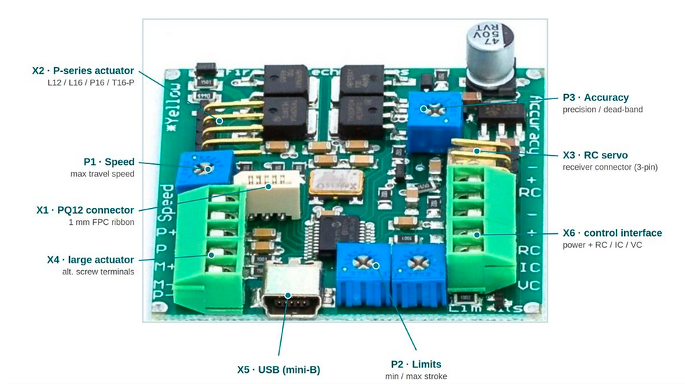
Control circuitry: On-board or external boards (such as a linear actuator control board) handle positioning, speed, and current limiting.
Common Engineering Questions
How do you adjust an actuator's stroke?
Most linear actuators do not have adjustable limit switches. Even so, you can constrain stroke length in several ways depending on your specific actuator: external limit switches, software limits in your controller code, or custom control-board settings.
What is the duty cycle of a linear actuator?
Duty cycle varies from device to device. There is no universal figure — always consult the manufacturer's specifications for your specific actuator before designing around continuous operation.
What happens if you run an actuator into a hard stop?
⚠ WARNING — AVOID HARD STOPS Running an actuator into a hard stop is one of the fastest ways to destroy it. It can cause motor failure, mechanical stress, overheating, and loss of accuracy — and it will shorten the life of the device. Always design your travel limits to stop short of the mechanical ends. |
Where Linear Actuators Are Used
Because they package precise, repeatable linear motion into a compact, controllable unit, linear actuators have spread across nearly every field that moves something in a straight line. Common domains include:
Aerospace: Flight surfaces, valves, and precision positioning where weight and reliability matter.
Medical devices: Patient positioning, diagnostic equipment, and lab automation that demand clean, controlled motion.
Robotics: Grippers, joints, linear stages, and autonomous platforms that need compact, repeatable actuation.
Industrial and consumer products: Automation, adjustable equipment, and any mechanism replacing manual cranking or pneumatics.
Bringing It Together
Once you can picture the chain — motor → gearbox → lead screw → nut → rod — the behaviour of a linear actuator stops being mysterious. The motor supplies rotation, the gearbox trades torque against speed, and the screw-and-nut pair converts that spin into clean linear travel inside a protective housing. Pick the gearing for your load, set sensible travel limits, and respect the duty cycle, and a linear actuator becomes one of the most dependable building blocks in motion design.
LOOKING FOR THE RIGHT ACTUATOR? Browse actuators by model or industry or get in touch to discuss your application. |
Comments